TFE Classic Renderer Complete
27 Dec 2020The 3D Object rendering system, derived from the original DOS code, is now working in both 320x200 (fixed-point sub-renderer) and at higher resolutions and in widescreen (floating-point sub-renderer). This completes the Classic Renderer reverse-engineering and integration project, allowing me to move on to reverse-engineering the INF system.
3D Object Renderer
The 3D object renderer in Jedi is basically an entire, mostly self-contained rendering system that integrates fairly well with the sector system. Models can either be drawn as points, though TFE turns these into quads at higher resolutions in order to maintain the same screen coverage, or as polygons. These polygons can either be triangles or quads, though there is little difference between the two forms in practice.
Each polygon can be shaded with one of five (5) variants: Color vertex shaded (“GOURAUD”), Color flat shaded (“FLAT”), Textured and vertex shaded (“GOURTEX”), Textured and flat shaded (“TEXTURE”), and finally textured as a floor or ceiling (“PLANE”). In the original executable, there are four (4) different clipping function variants and five (5) different polygon draw variants resulting in thousands of lines of C-code. In TFE, macros are abused in a method most likely similar to the original code to reduce these down to a master clipping routine, which is then instantiated four times using defines and two polygon rendering routines - one to handle the “PLANE” case and one to handle every other case.
For TFE integration, I have split the original rendering code into several components to make following and maintaining the code easier. I will go through each component below.
Transform And Lighting
3D objects in Jedi have a 3x3 rotation matrix and a 3D position. The main renderer generates a 3x3 camera matrix for use by the 3D object renderer. The object position is transformed into viewspace and the object/camera matrices are concatenated to build a single local to viewspace rotation matrix. The final matrix (“transform matrix”) and viewspace offset (“offset”) are used from here on in all transformations.
Next, all of the modelspace positions are transformed into viewspace. It is at this point the transform and lighting stage end if the “MFLAG_DRAW_VERTICES” flag is set, which causes the object to be rendered as points. Otherwise, the model has a list of polygon normals that were precalculated on load and these are now transformed into viewspace. These normals will be used later for backface culling.
Finally, if vertex shading is required - that is any polygon uses “GOURAUD” or “GOURTEX” for its shading - the vertex normals, also computed on load, are transformed into viewspace. Once that is done, per-vertex lighting is applied.
Lighting
The Jedi Engine supports multiple directional lights, each with its own direction and brightness values. For Dark Forces this is setup as 3 directional lights, each in a cardinal direction (X, Y, Z). The lighting contribution for each light is summed up for the vertex and then the sum is multiplied by the “sector ambient fraction” - which is the fraction of sector ambient compared to the maximum. The maximum ambient light level for any sector is 31 (0x1f), so a sector with an ambient of 22 would have a value of approximately 0.71 for its “sector ambient fraction.”
The next step is to apply lighting from the camera light source, such as the headlamp (by default this is turned off). This uses a special light source ramp that is embedded in the level’s color map. This is a 128 entry table, indexed by the current depth: depthIndex = min( floor(z * 4), 127 ); the table itself is inverted. The final value of the camera light for the current depth is: MAX_LIGHT_LEVEL - (s_lightSourceRamp[depthIndex] + s_worldAmbient). Normally this is done per-column or scanline, but in the case of vertex-lighting, it is done per-vertex.
The final step is to apply a falloff value based on distance, similar to the distance-based darkening in Doom or Duke3D. The current depth (Z) value is scaled and then subtracted from the intensity calculated so far. However to avoid the brightness changing too much, the overall lighting value is clamped to a range of [Sector Ambient, 0.875*Sector Ambient].
Backface Culling
If the “MFLAG_DRAW_VERTICES” flag is set, then the model will draw the vertices at this point and then the object drawing is complete. Otherwise the renderer moves on to the next step - backface culling. This step has two tasks, 1) determine which polygons are facing towards the camera, which are added to a list of potentially visible polygons and 2) determine the average depth (Z) value for each polygon for later sorting and lighting if flat shading is used (“FLAT” or “TEXTURE”).
Once the potentially visible set of polygons has been determined, they are sorted from back to front based on their average depth value.
Polygon Drawing
At this stage, the code loops through the visible polygons, skipping past any with too-few vertices. Drawing each polygon requires several steps:
Setup
The required vertex attributes to draw the polygon are copied into flat arrays which will be used directly for several reasons: to avoid indexing into the larger list, and the arrays are mutable, allowing the clipping routines to change and add values without modifying the larger data set. If the shading mode requires texture coordinates, they are copied from the polygon into the array. If vertex shading is required, the intensity values calculated during the Transform and Lighting step are copied.
Clipping
Next polygons are clipped against five (5) frustum planes: the near plane (at Z = 1.0), left, right, top, and bottom planes. In TFE, float-point sub-renderer, the left and right planes are adjusted based on the (potentially) widescreen aspect ratio. The top and bottom planes are computed, taking into account the sheared perspective. Given a convex polygon as input, the result will be a complex polygon or be discarded - which happens when a polygon is fully behind a plane.
Drawing
If the polygon survives clipping, its vertices are projected into screenspace and then drawing can begin. If flat shading is used, a single color or intensity value is generated for the polygon using the procedure described in the Lighting section above. In this case the polygon normal and average Z value is used.
The first four variants generate columns while the “PLANE” shading mode generates scanlines. For the column drawers, the screenspace bounding box is computed for the polygon and then edges are scanned starting starting from the minimum X value. Matching edges are scanned backwards and forwards and as the code steps along the edges, columns are computed.
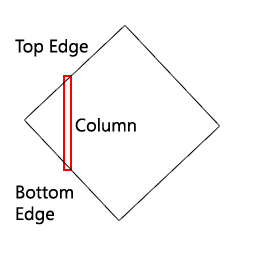 You can see in the image the “top edge” (forward) and “bottom edge” (backward). Given two edges, the code steps forward in X and vertex values are computed at each point by linearly interpolating along these edges. Once we move past an edge, the next one is found and this continues until we run out of edges.
At each X value, we setup a column. The Z (depth) value is the minimum of the Z along each edge. This Z value is compared to the 1D depth buffer previously generated by the sector walls in order to sort the columns with the walls. Columns are also clipped to the current vertical window and columns are discarded if they are outside of the horizontal window. Finally the vertex values are interpolated along the column using one of the specialized column drawing routines. If vertex shading is used for lighting, a screenspace dither value is used to breakup the edges between light levels.
The scanline case is very similar but rotated on its side (minimum Y instead of X, stepping along Y, etc.). The difference with the “PLANE” mode is that it doesn’t use existing texture coordinates. Rather, once the scanlines are generated, they are clipped and rendered in the same way as the flats (floors and ceilings).
Conclusion
This is obviously a very brief description of the rendering process, but as you can see it was pretty advanced for the time. Unfortunately the lighting rig was underutilized, they simply stuck with 3 axis aligned directional lights at full brightness. It might be interesting to make this functionality accessible by modders in order to enhance the mood of their levels. However, this lighting rig only affects 3D objects.
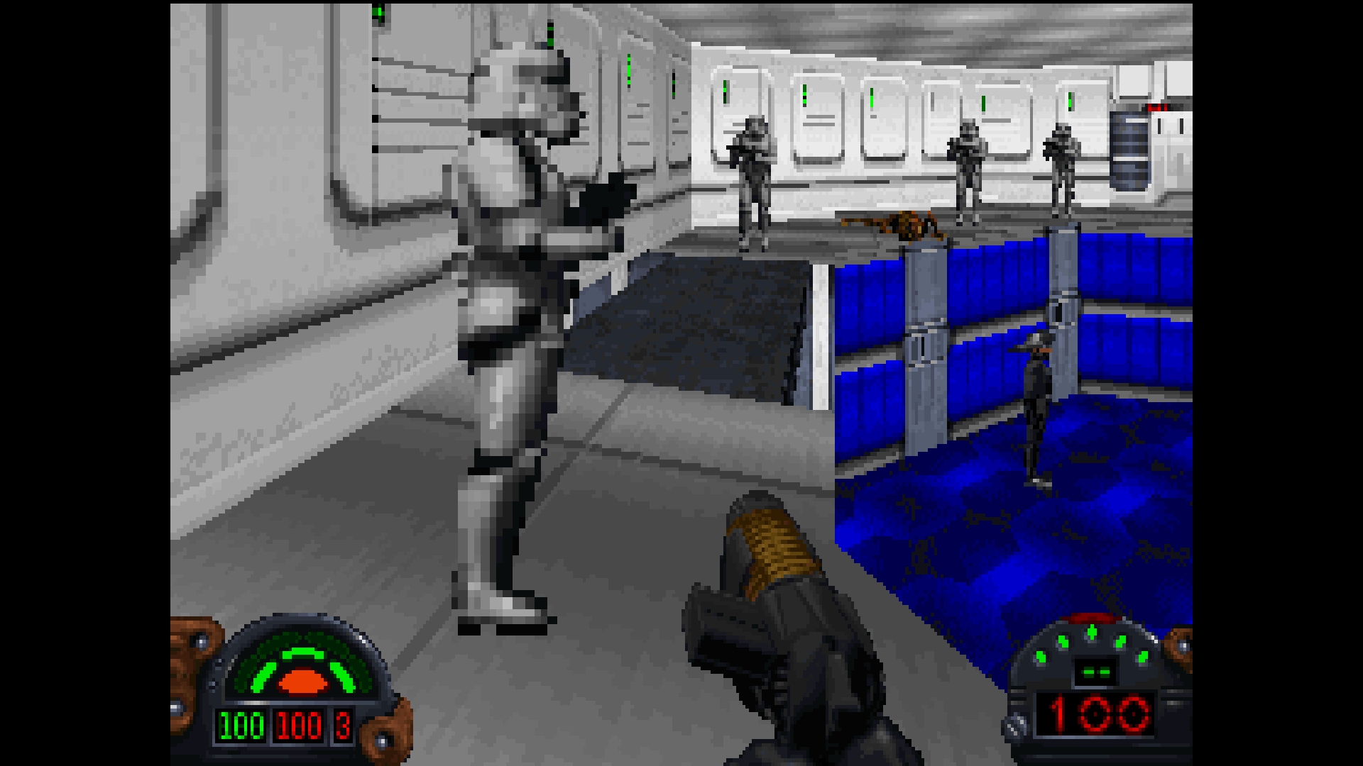
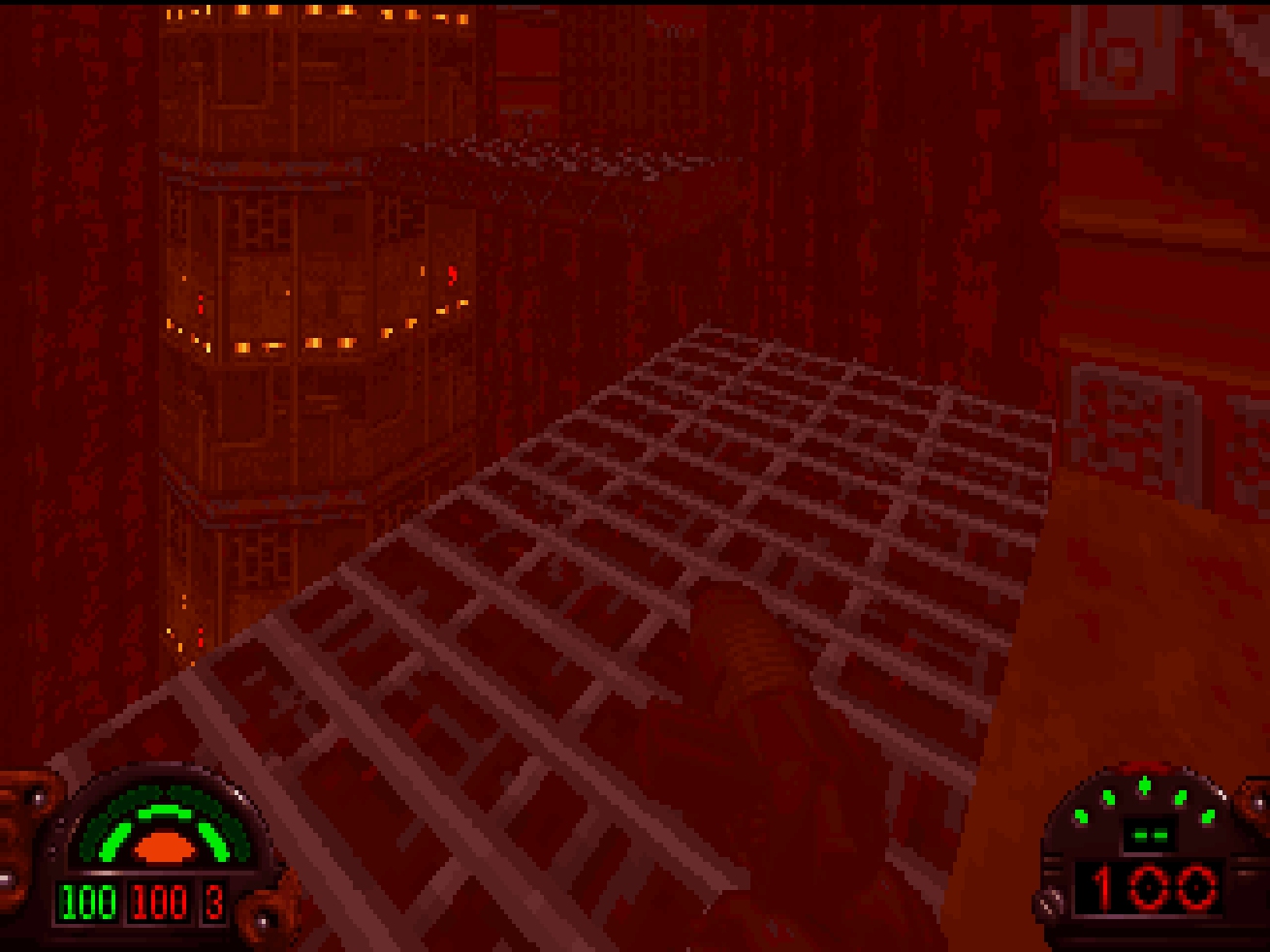
Screenshots
Issues and Bugs
The Classic Renderer will have bugs, the 3D object rendering code itself is about 3k lines of code and is less than half the size of the sector and sprite rendering code. However, some issues are due to the way objects are assigned and offsets are calculated as part of the INF setup. So, in other words, the Classic Renderer will not look 100% correct until the INF system is reverse-engineered.
Next Steps
The existing INF system in the test release was written based on my understanding of the INF system in the original game which obviously still has gaps. The next step is to replace that system with directly reverse-engineered code, which will be tested heavily with mods as well as the original levels. Once this is complete, almost all mods should be playable with TFE - with the caveat, of course, that the AI will still be placeholder (i.e. just stand around waiting to be killed) - but the correct events will fire.